Modding: Putting an ATX system into a Apple PowerMac G5 Case - Mark I
I have always liked Apple computer systems. My faves are the Apple PowerMac, the G4 cube and the Apple G3 powerbook (you know, the black one). Unfortunately I have never been able to afford them. As such I decided on the next best thing, putting a normal PC into a Mac Case. A few years later and a job, I had enough money to start the project and as such I bought a damaged G5 Powermac case from an apple repair store. Cosmetically it was in ok condition (a few scratches here and there, and some dents), but the wiring inside was badly damaged. As I will not be using most of the original wiring, this is a minor inconvenience.
Goals
- I want the case to look authentic, I don't want to make any modifications to the exterior. It should look exactly like a Mac from the outside.
- Quietness. I want the machine to be as near silent as possoble. I realise that total silence is impossible with my budget, but likewise it should not sound like a jet taking off. Thankfully the Apple case already goes to great length to minise noise.
First stage: Installing the Motherbard, ATX PSU and Drives
I ended up installing the ATX components into the Apple case. The hardest thing was to work out how to wire it all. The Apple case does not follow the ATX standard for components, so I could not just use a normal backplate for the connections. But at the same time, I don't want to alter the case, I want it to look as authentic as possible.
In the end I installed the motherboard in the case at 90 degrees to normal, so all the connections point towards the bottom of the case, and the wires come out of gaps at the bottom (usually for the PSU plug) and the slots at the top of the case. Thats all I did for now, here is a picture if you are having trouble visualising it:
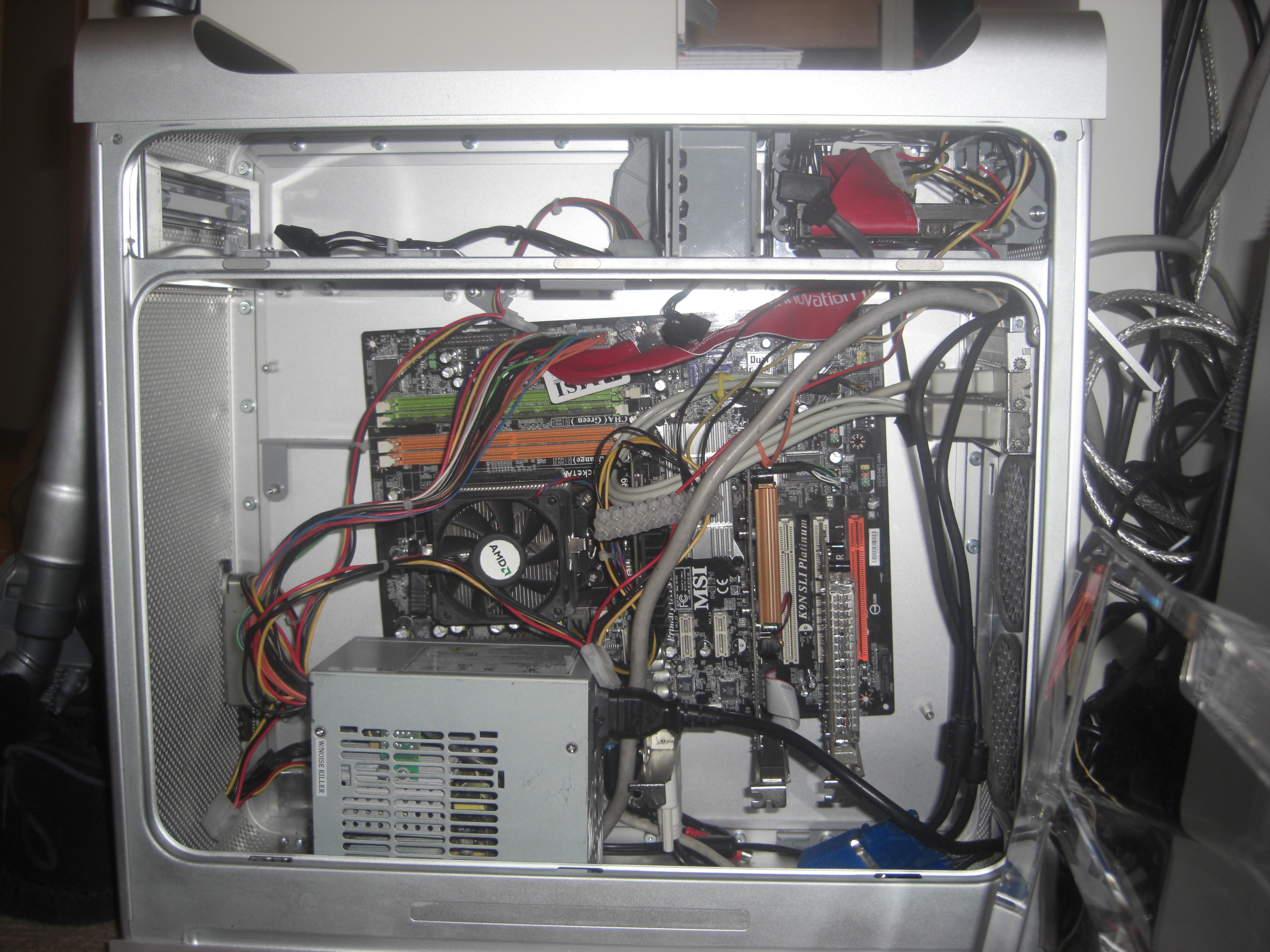
The motherboard was mounted to whatever holes I could get aligned. As a result it is a bit wonky, but it worked. You need at least 2 holes to align to be able to mount the motherboard. I also had to take care not to short anything out. The hard drive is in the original location at the top-right hand corner.
As you can see, there is still a lot of work to do, but it works for now, which was my goal. I will make a proper motherboard mount when I get my new rotary tool (my old one had given up on me a while back).
January 2009
Got myself a new rotary tool, a Dremel 300. The difference between it and my previous clone is amazing. It's so much better, and well worth the extra cost. Anyway, more changes to this project.
Now that I have a good rotary tool, I decided to mount the motherboard properly. The case is not designed for ATX, so a lot of the mounting holes are in the wrong place. My first plan was to make a flange out of acrylic sheet, with standoffs for ATX and holes for the local mount points. However The problem here is the motherboard ends up being 3-4 centimeters higher than the rear slots, so I could not mount it externally without cutting.
As I did not want to cut it out, I once again set the motherboard further inwards. As things stand, once wired up I don't really plug/unplug components (apart from USB devices), so having all the connectors internal was not as much a headache as it sounds.
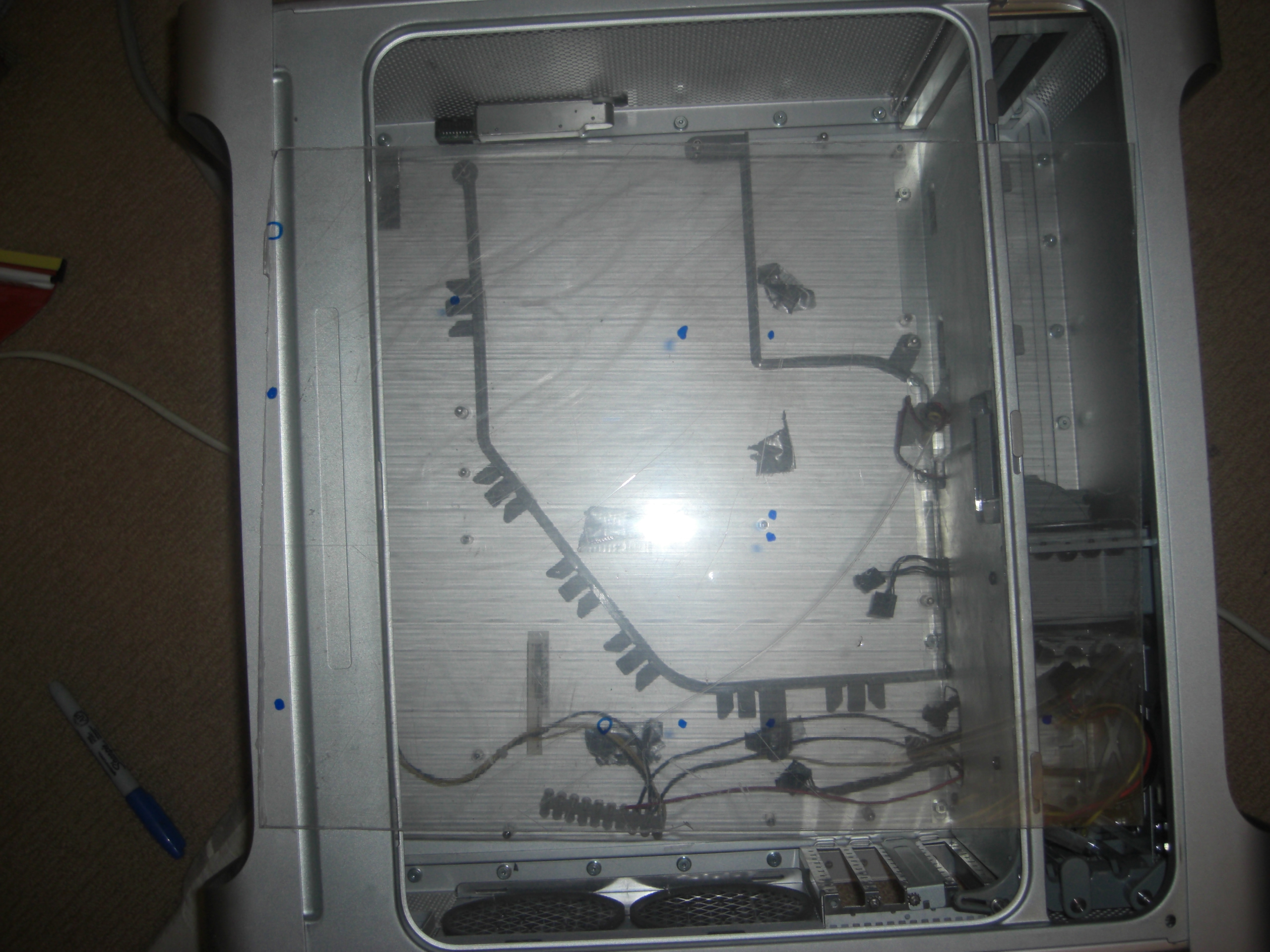
As such, I decided to make the flange. It will have two sets of holes. One set connects the plexiglass to the G5 case, the other set connects the plexiglass to the motherboard. I deliberately used transparent acrylic sheet because it is easy to mark holes. You just offer it up to the case, see where the mounts are, and draw circles around it, as shown below:
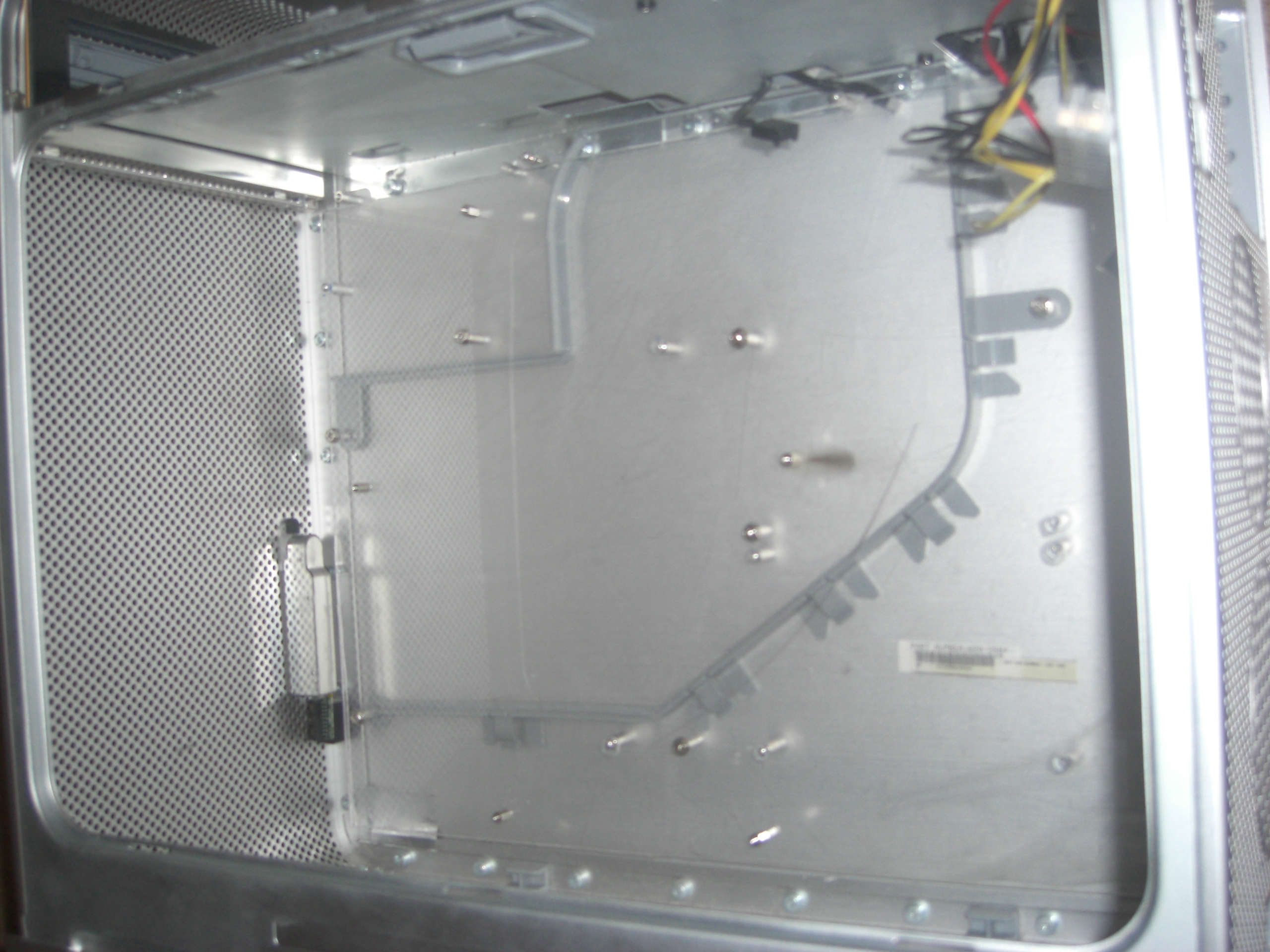
Once marked out, I drilled two sets of mounting holes. Then I mounted the acrylic sheet into the G5 case, and inserted standard ATX motherboard standoffs. The end result:
Looking pretty good so far! Next stage is to mount the motherboard and all ancilliaries. At this point one problem came to mind. As a result of keeping the motherboard inwards is there was nowhere to mount the expansion cards to. Therefore I had to cutout another strip of acrylic, and attach it to the roof of the top shelf, to which I could then attach the expansion cards.
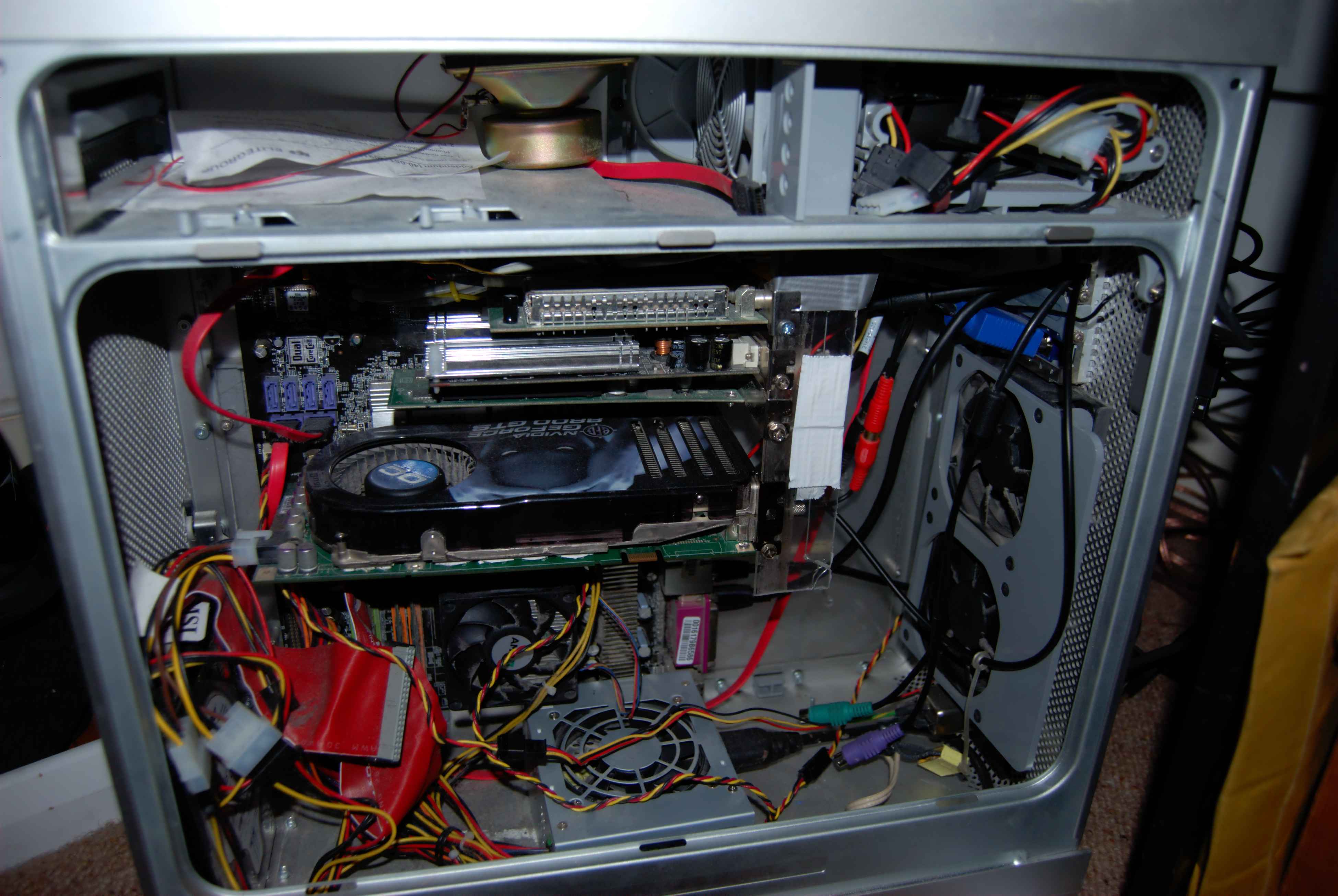
The end result, with everything installed and running:
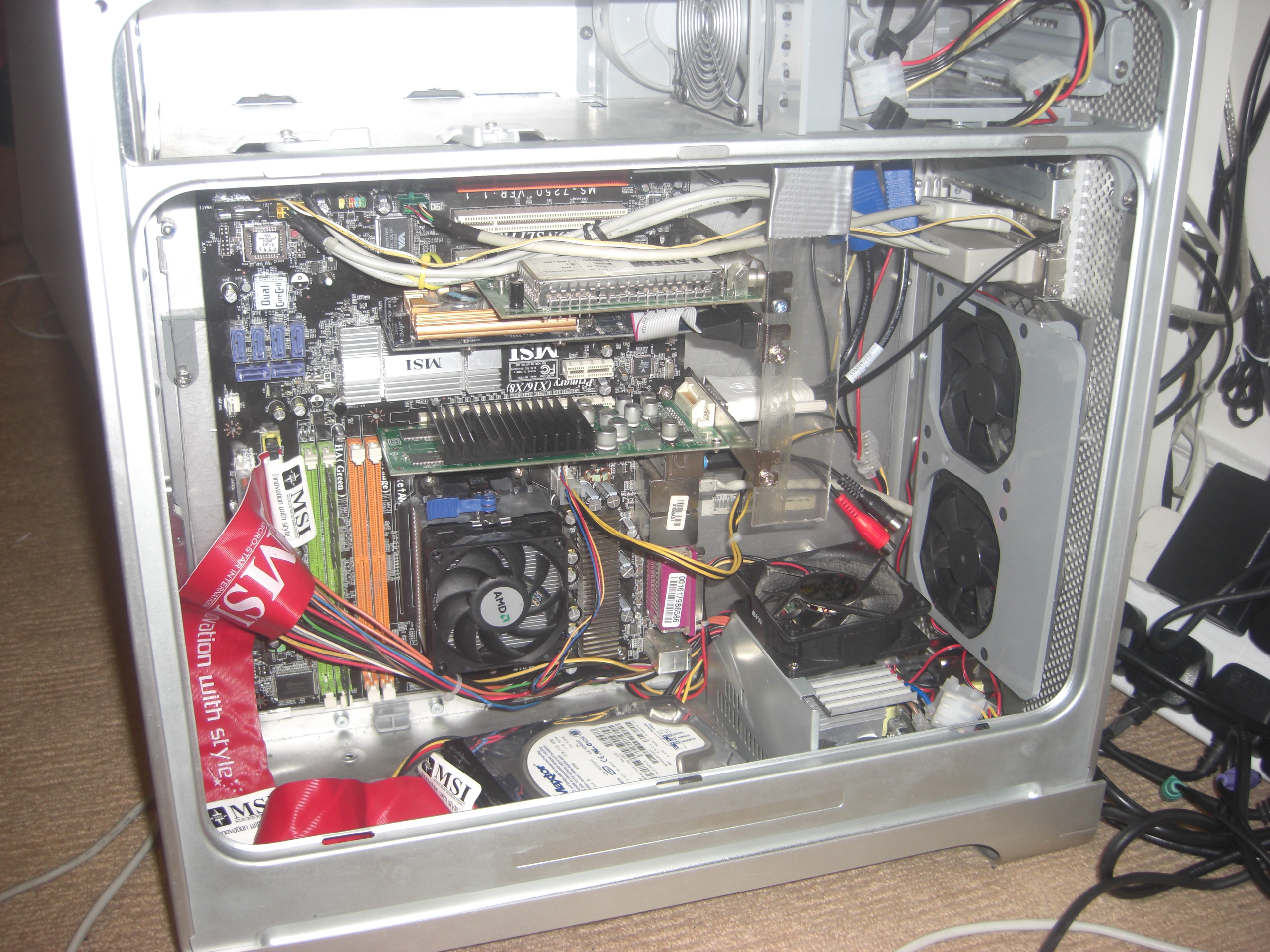
Yes, I used duct tape to attach the expansion card strip :-) It works! The mounting of all the cards to the strip also gave it good rigidity, so this was a pretty good set up.
I moved the IDE drive to the bottom as I've bought a SATA disk, and when it arrives I will put it into the bay at the top were it should be.
The PSU is mounted just behind the motherboard (AMD Dual Core, 8GB RAM). Top PCI card is a TV capture card, below is my Nvidia GeForce 8600GS that I use for CUDA Work, and below that is my Quadro (NV 44) which drives my dual 19-inch monitors. The fans at the top do not work yet, so I'm avoiding putting any drives up there until I get some airflow.
The original fans at the back were burnt out, so I have to get some new ones, till then I shall be using some smaller fans that I had kicking around.
So far the case is doing very well. It is not silent, and it's not exactly quiet either, but the airflow that the case allows through it is impressive. So far the entire system never goes past 55 degrees celcius as a whole, even when it's pushed to it's limits. I'll work on quietning all the fans later on.
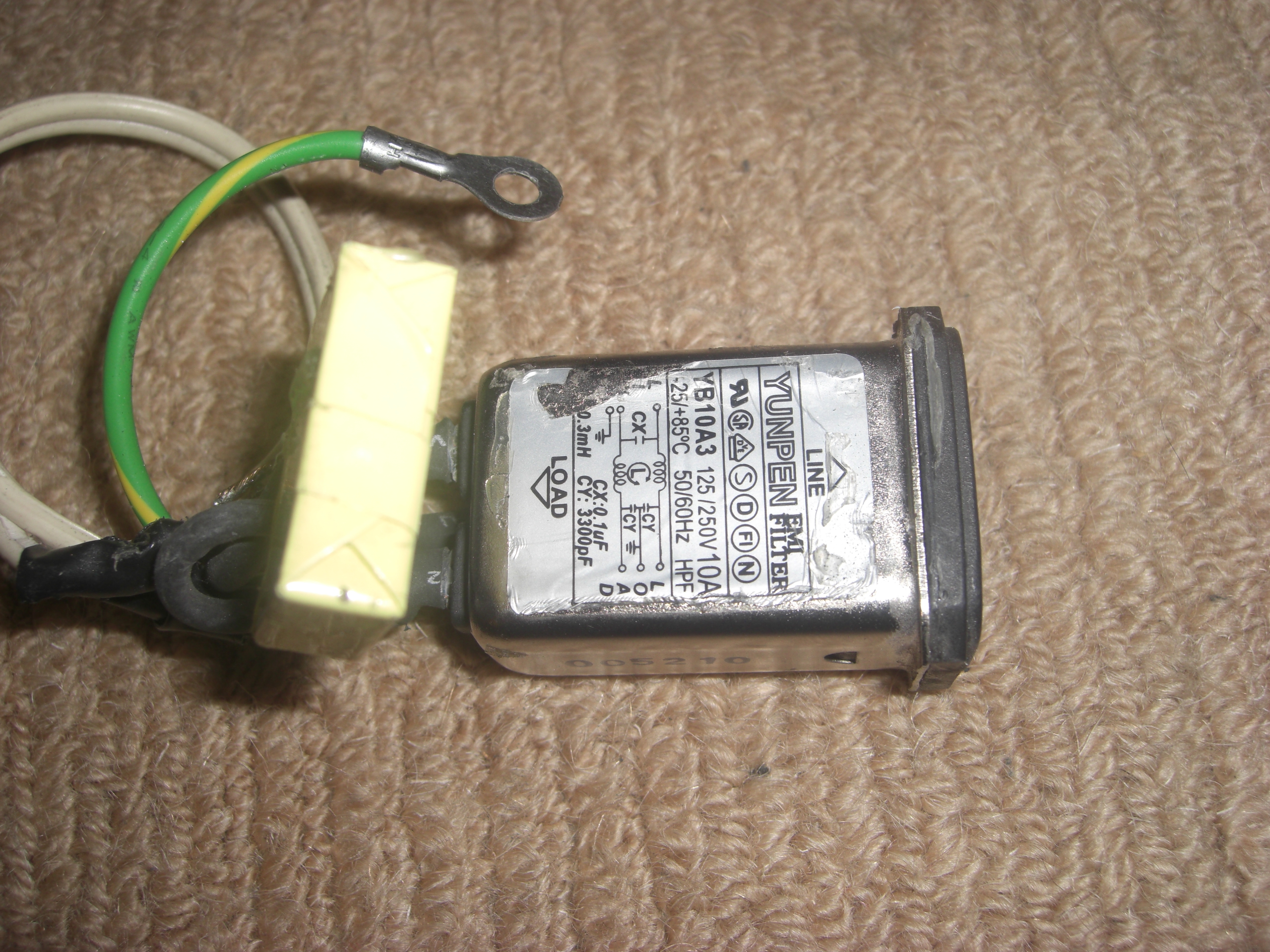
Although not everything went smoothly. In order for this new layout to work, I had to reduce the height of the PSU (because it could not fit under the fans). I removed the PSUs cover, and this allowed me to slip it underneith the fans. I also wanted the power socket to be in the same place as the original G5, so I removed the PSUs power socket, cut off the ends and installed it in the existing hole. With the PSU case off, this necessated good grounding with the case (it being metal as well, you would be one accident away from electrocution).
The PSU socket with the sides cut off so that it would fit.
The socket mounted in the G5 case:
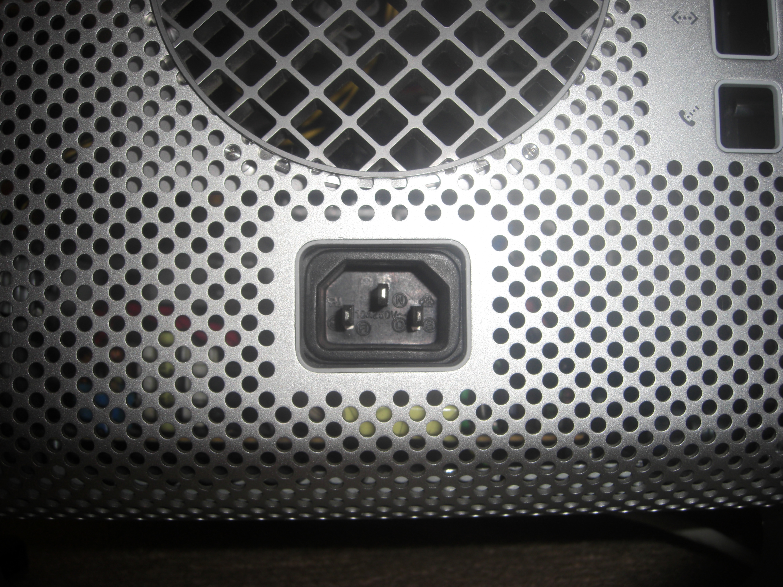
The PSU was grounded to the case, and the case was grounded to the ground pin on the socket. The G5 has had a nice threaded stud at the bottom I could use for grounding.
September 2009
A new GPU was installed (BFG GeForce 8800GTS) and with it, a new PSU was bought and installed. I needed a more powerful one, so went looking. My gf was far better at this than me, as she found an excellent 700W micro-ATX PSU, which was both more powerful, and smaller than the old one. I bought and installed it. It worked perfectly:
By virtue of moving the PSU to where the old HD was, I had to temporarily shove the HD into the corner in the messy way you see above. Despite this overall the system stayed pretty cool, although the 8800GTS's fan was really noisy, especially when it was running CUDA programs full tilt.
Also, by having a fully enclosed PSU the chances of getting a nasty shock were reduced, which is always a benefit :)
At this point it became possible to close up the case and have it actually look like a PC rather than a perpetually half finished project.
February 2011
So, the machine in its above form has lasted until now, I guess part of it was due to the fact the machine actually worked, and when closed it was "good enough" that me using it was more important than me fiddling with it as a project.
However with the purchase of a dual-core laptop that was pretty powerful in its own right (good enough to be used as a primary PC), I could swith to that for a while, and I went back to fiddling with this one.
And with that, the G5 ATX Mod "Mark II" began :-)


